CHIP-8 is an interpreted programming language, developed by Joseph Weisbecker. It was initially used on the COSMAC VIP and Telmac 1800 8-bit microcomputers in the mid-1970s. CHIP-8 programs are run on a CHIP-8 virtual machine. It was made to allow video games to be more easily programmed for said computers.
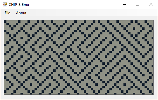
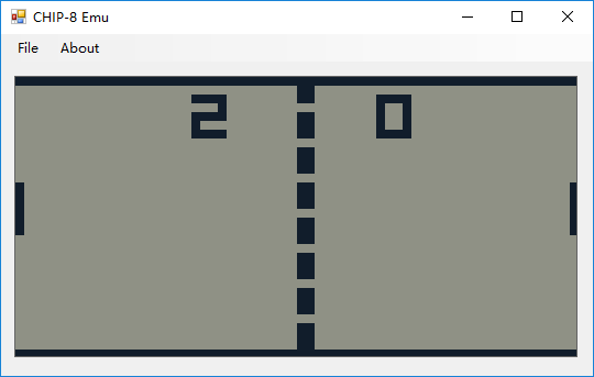
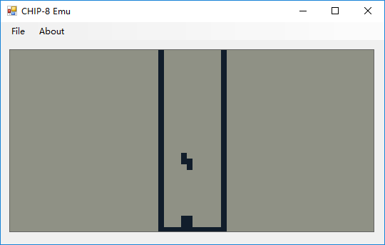
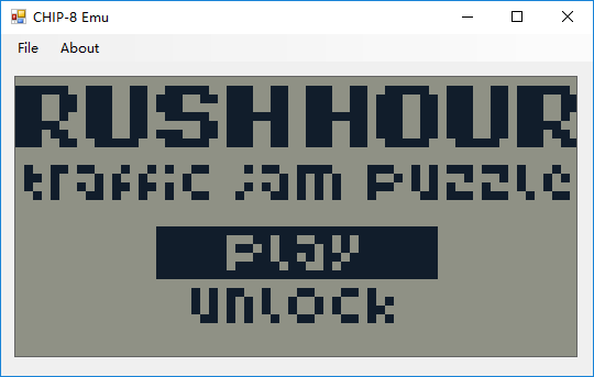
没错,上面这些是从wikipedia上复制过来的.这两天我就亲自实现了一下,先看看运行效果.
源码我放在github上了.https://github.com/veritas501/CHIP-8_Emulator
硬件
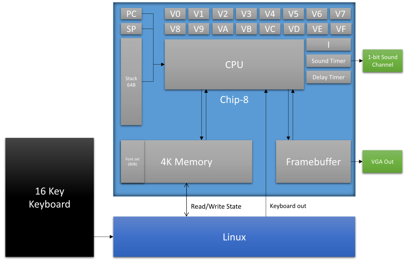
寄存器
V0~VF是16个1byte的寄存器,其中VF也用做进位,借位等特殊操作的标志位.
I是索引(index)寄存器,2byte长度.相当于一个pointer的作用.
Sound Timer(ST)和Delay Timer(DT)是两个1byte的寄存器,他们都是以60Hz的速度递减1,当减到0就停止,略有不同的是DT只是简单的停下,而ST在非0时,1bit的Sound Channel会发出声音.
PC就是我们熟知的Program Counter,程序计数器,2bytes长度.
SP就是我们熟知的Stack Pointer,2bytes长度.
内存
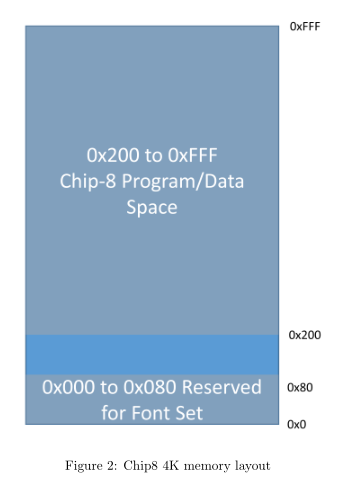
程序预留了4K(0x1000bytes)的空间当作主要存储空间,其中0x0~0x200都是做字体用.
4x5 low-res 字体编码方式:
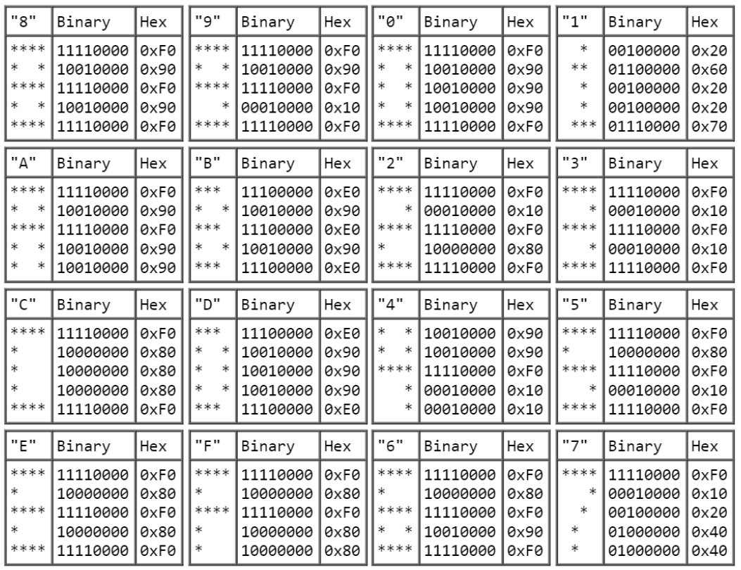
0x0~0x200的这部分内存我直接从https://github.com/massung/CHIP-8处拷贝过来了,偷了个懒.这个作者还做了8*10 high-res的字体,以及后面还编码了一些貌似用不到的字体.
64bytes的空间做栈.就不多解释了.
64*32(屏幕尺寸)bits的空间做Framebuffer.每次对framebuffer做修改时,并不是对指定bits直接置1或是置0,而是对他做一个异或(new = set^old)
外设
需要映射16key(0~F)的键盘,1bit Sound Channel,以及用于显示的屏幕.
CHIP-8内部的键盘布局是这样的:
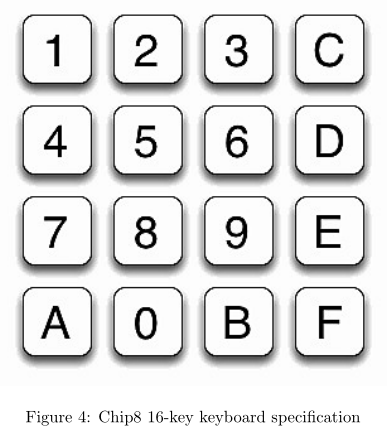
对此,我们可以从上到下,从左到右,映射为
1 | 1 2 3 4 |
屏幕的显示可以用picturebox来实现.
指令集
CHIP-8的指令是定长的,为2字节.
- 0nnn - SYS addr
Jump to a machine code routine at nnn. This instruction is only used on the old computers on which Chip-8
was originally implemented. It is ignored by modern interpreters. This will not be implemented.
我们无需实现,可以当nop处理.
- 00E0 - CLS
Clear the display.
清除显存.
- 00EE - RET
Return from a subroutine.The interpreter sets the program counter to the address at the top of the stack,
then subtracts 1 from the stack pointer.
1 | PC = stack[SP--]; |
- 1nnn - JP addr
Jump to location nnn. The interpreter sets the program counter to nnn.
1 | PC = 0xnnn; |
- 2nnn - CALL addr
Call subroutine at nnn. The interpreter increments the stack pointer, then puts the current PC on the top
of the stack. The PC is then set to nnn.
1 | stack[++SP] = PC; |
- 3xkk - SE Vx, byte
Skip next instruction if Vx = kk. The interpreter compares register Vx to kk, and if they are equal,
increments the program counter by 2.
1 | if(Vx == kk) PC+=2; |
- 4xkk - SNE Vx, byte
Skip next instruction if Vx != kk. The interpreter compares register Vx to kk, and if they are not equal,
increments the program counter by 2.
1 | if(Vx != kk) PC+=2; |
- 5xy0 - SE Vx, Vy
Skip next instruction if Vx = Vy. The interpreter compares register Vx to register Vy, and if they are equal,
increments the program counter by 2.
1 | if(Vx == Vy) PC+=2; |
- 6xkk - LD Vx, byte
Set Vx = kk. The interpreter puts the value kk into register Vx.
1 | Vx = kk; |
- 7xkk - ADD Vx, byte
Set Vx = Vx + kk. Adds the value kk to the value of register Vx, then stores the result in Vx.
1 | Vx += kk; |
- 8xy0 - LD Vx, Vy
Set Vx = Vy. Stores the value of register Vy in register Vx.
1 | Vx = Vy; |
- 8xy1 - OR Vx, Vy
Set Vx = Vx OR Vy. Performs a bitwise OR on the values of Vx and Vy, then stores the result in Vx. A
bitwise OR compares the corresponding bits from two values, and if either bit is 1, then the same bit in the
result is also 1. Otherwise, it is 0.
1 | Vx |= Vy; |
- 8xy2 - AND Vx, Vy
Set Vx = Vx AND Vy. Performs a bitwise AND on the values of Vx and Vy, then stores the result in Vx.
A bitwise AND compares the corresponding bits from two values, and if both bits are 1, then the same bit
in the result is also 1. Otherwise, it is 0.
1 | Vx &= Vy; |
- 8xy3 - XOR Vx, Vy
Set Vx = Vx XOR Vy. Performs a bitwise exclusive OR on the values of Vx and Vy, then stores the result
in Vx. An exclusive OR compares the corresponding bits from two values, and if the bits are not both the
same, then the corresponding bit in the result is set to 1. Otherwise, it is 0.
1 | Vx ^= Vy; |
- 8xy4 - ADD Vx, Vy
Set Vx = Vx + Vy, set VF = carry. The values of Vx and Vy are added together. If the result is greater
than 8 bits (i.e., ¿ 255,) VF is set to 1, otherwise 0. Only the lowest 8 bits of the result are kept, and stored
in Vx.
1 | VF = (Vx > 255 - Vy) ? 1 : 0; |
- 8xy5 - SUB Vx, Vy
Set Vx = Vx - Vy, set VF = NOT borrow. If Vx ¿ Vy, then VF is set to 1, otherwise 0. Then Vy is
subtracted from Vx, and the results stored in Vx.
1 | VF = (Vx > Vy) ? 1 : 0; |
- 8xy6 - SHR Vx {, Vy}
Set Vx = Vx SHR 1. If the least-significant bit of Vx is 1, then VF is set to 1, otherwise 0. Then Vx is
divided by 2.
1 | VF = (Vx & 1) ? 1 : 0; |
- 8xy7 - SUBN Vx, Vy
Set Vx = Vy - Vx, set VF = NOT borrow. If Vy ¿ Vx, then VF is set to 1, otherwise 0. Then Vx is
subtracted from Vy, and the results stored in Vx.
1 | VF = (Vy > Vx) ? 1 : 0; |
- 8xyE - SHL Vx {, Vy}
Set Vx = Vx SHL 1. If the most-significant bit of Vx is 1, then VF is set to 1, otherwise to 0. Then Vx is
multiplied by 2.
1 | VF = (Vx >> 7) ? 1 : 0; |
- 9xy0 - SNE Vx, Vy
Skip next instruction if Vx != Vy. The values of Vx and Vy are compared, and if they are not equal, the
program counter is increased by 2.
1 | if(Vx != Vy) PC += 2; |
- Annn - LD I, addr
Set I = nnn. The value of register I is set to nnn.
1 | I = nnn; |
- Bnnn - JP V0, addr
Jump to location nnn + V0. The program counter is set to nnn plus the value of V0.
1 | PC = V0 + nnn; |
- Cxkk - RND Vx, byte
Set Vx = random byte AND kk. The interpreter generates a random number from 0 to 255, which is then
ANDed with the value kk. The results are stored in Vx. See instruction 8xy2 for more information on AND.
1 | Vx = randnum & kk;//randnum: 0 ~ 255 |
- Dxyn - DRW Vx, Vy, nibble
Display n-byte sprite starting at memory location I at (Vx, Vy), set VF = collision. The interpreter reads n
bytes from memory, starting at the address stored in I. These bytes are then displayed as sprites on screen
at coordinates (Vx, Vy). Sprites are XOR’d onto the existing screen. If this causes any pixels to be erased,
VF is set to 1, otherwise it is set to 0. If the sprite is positioned so part of it is outside the coordinates of
the display, it wraps around to the opposite side of the screen.
这个指令有点复杂,解释一下,framebuf是bit为单位的.
从memory[I]取出1byte,展开为8bits:7654 3210,
framebuf[Vx+0,Vy] ^= bit7;
framebuf[Vx+1,Vy] ^= bit6;
…
framebuf[Vx+7,Vy] ^= bit0;
这么一步操作是1nibble.
假设此处传进来的nibble是2,那么下一步就是从memory[I+1]取出1byte,展开为8bits,
framebuf[Vx+0,Vy+1] ^= bit7;
framebuf[Vx+1,Vy+1] ^= bit6;
…
framebuf[Vx+7,Vy+1] ^= bit0;
在整个操作中,如果framebuf有一个bit从1变成了0,那么设置VF为1,否则为0.
- Ex9E - SKP Vx
Skip next instruction if key with the value of Vx is pressed. Checks the keyboard, and if the key corresponding
to the value of Vx is currently in the down position, PC is increased by 2.
1 | if(key[Vx]){//pressed |
- ExA1 - SKNP Vx
Skip next instruction if key with the value of Vx is not pressed. Checks the keyboard, and if the key
corresponding to the value of Vx is currently in the up position, PC is increased by 2.
1 | if(!key[Vx]){//unpressed |
- Fx07 - LD Vx, DT
Set Vx = delay timer value. The value of DT is placed into Vx.
1 | Vx = DT; |
- Fx0A - LD Vx, K
Wait for a key press, store the value of the key in Vx. All execution stops until a key is pressed, then the
value of that key is stored in Vx.
1 | for (byte i = 0; i < 0x10; i++) |
- Fx15 - LD DT, Vx
Set delay timer = Vx. Delay Timer is set equal to the value of Vx.
1 | DT = Vx; |
- Fx18 - LD ST, Vx
Set sound timer = Vx. Sound Timer is set equal to the value of Vx.
1 | ST = Vx; |
- Fx1E - ADD I, Vx
Set I = I + Vx. The values of I and Vx are added, and the results are stored in I.
1 | I += Vx; |
- Fx29 - LD F, Vx
Set I = location of sprite for digit Vx. The value of I is set to the location for the hexadecimal sprite
corresponding to the value of Vx. See section 2.4, Display, for more information on the Chip-8 hexadecimal
font. To obtain this value, multiply VX by 5 (all font data stored in first 80 bytes of memory).
将Vx的值所对应的字体在内存中的位置赋给I.由于0~F在内存中是按顺序存储在开头的80字节中.
1 | I = Vx * 5; |
- Fx33 - LD B, Vx
Store BCD representation of Vx in memory locations I, I+1, and I+2. The interpreter takes the decimal
value of Vx, and places the hundreds digit in memory at location in I, the tens digit at location I+1, and
the ones digit at location I+2.
1 | Mem[I + 0] = (byte)((Vx / 100) % 10); |
- Fx55 - LD [I], Vx
Stores V0 to VX in memory starting at address I. I is then set to I + x + 1.
1 | for (byte i = 0; i <= x; i++) |
- Fx65 - LD Vx, [I]
Fills V0 to VX with values from memory starting at address I. I is then set to I + x + 1.
1 | for (byte i = 0; i <= x; i++) |
具体实现
见github源码吧.
https://github.com/veritas501/CHIP-8_Emulator
参考
https://en.wikipedia.org/wiki/CHIP-8
http://www.cs.columbia.edu/~sedwards/classes/2016/4840-spring/designs/Chip8.pdf
https://github.com/massung/CHIP-8